Meet the 2022 Senior Design Teams
Senior Design is a year-long course required for all engineering seniors to graduate. Each team of 3-7 seniors is mentored by both the Engineering faculty and their project sponsor.
Sponsors gain the first-hand experience of working with potential future employees to see their project to fruition. Our seniors hone their collaborative team skills while fulfilling their commitment to creating real-life deliverables for their sponsors.
Meet the Teams
-
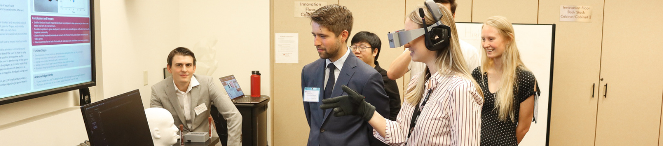
Inclusive Gaming: Developing a Non-Visual Experience
Sponsor: Blind Institute of Technology
Team: Chris Grauberger (Team Captain), Justin Bilello, Haibing Huang, and Jessie Scrivner
Over 250 million people worldwide have some form of visual limitation. Despite regulatory measures such as the Americans with Disabilities Act (ADA), blind and visually impaired individuals still find themselves unable to participate in many activities that others take for granted, including video games. Video game development is a $200 billion-dollar-a-year industry that has recently made significant strides in the inclusion of those with physical disabilities. However, there are very few games and controllers designed for individuals with visual impairments, and it is disappointing to see how little has been done to provide blind consumers with inclusive options.
The objective of this project was to design a controller that provides non-visual (audio and haptic) feedback to the video game user. To achieve this objective a wearable device was developed that uses multiple motors and sensors to deliver audio and haptic feedback to the user and to collect data from the user’s movements. Wireless surround sound headphones provide audio feedback to the user and serve to direct the user on how to play the game and will provide positive or negative audio feedback based on the user’s performance in the game. Haptic motors attached to the glove provide haptic feedback to the user and serve to direct the player's actions by indicating what action should be taken and in which direction based on where on the hand different vibrations happen. The haptic motors also inform the user with feedback on how they are performing in the game using over 100 different vibration effects. Another aspect of our design is how the user controls the game. 3 bend sensors on the thumb, pointer finger, and middle finger and an IMU on each hand allow the user to control the game using nothing but their hands. These sensors allow the user's finger movements, hand movements, speed, and motions to be tracked which are then used as the controls of the game.
This technology could lead to large game developers including blind accessibility features in popular games. This system would allow online interaction and in-person experiences for a large group of people that would otherwise not be possible. More advanced gaming systems of this design could also be folded into game controllers in general for Virtual Reality (VR) to create a more immersive experience for any player. It could also be applied to traditional controllers to provide a more descriptive feedback process for lots of applications, such as household appliances or heavier equipment. More accessibility in technology, in general, would lead to more independence for people who rely on assistive technology in their everyday life.
-
In-Lab Alpine Simulator
Sponsor: BOA Technology
Team: Ryan Knowles, Kayle Migaki, Guy Milliman, Bradley Orsini, and Noah Sung
BOA Technology is a global company dedicated to improving athletic performance. It is best known for its groundbreaking ‘Fit System,’ which combines a micro-adjustable dial, super-strong lightweight laces, and low-friction lace guides to provide athletes with precise control of footwear fit. A research team at BOA’s headquarters in Denver, Colorado studies the biomechanical impact of fit in a variety of sporting activities, including skiing and snowboarding. Research in winter snow-sports is limited by unique challenges, including seasonal variable weather conditions, inflated costs, long distances/travel times, and the inability to transport laboratory equipment (camera-based motion capture system, force plates) to the mountains. To address these limitations, this senior design team was tasked with building an In-Lab Alpine Simulator that, when used in combination with insole pressure mapping tools, gives BOA researchers the opportunity to investigate snow-sports in a laboratory setting.
The team’s In-Lab Alpine Simulator includes a revolving carpet with a controllable speed (0-12.5 mph) and inclination angle (9.5-17.5°). The footprints of the entire system and the skiable area are approximately 10ft x 14ft and 7.7ft x 12.2ft (LxW), respectively. The design favors width over length so that users can make carving turns that mimic those made on a mountain slope. The main substructure is constructed with A36 Steel to provide strength and stability. The electrical system requires a 208 V input (3 PH), which is maintained through three components: the disconnect switch, variable frequency driver (VFD), and motor. Each component protects the next from a current surge, with the disconnect switch (50 A) protecting the VFD (32 A) and the VFD protecting the motor (27.5 A). The team’s prototype costs roughly $16,500, making it significantly cheaper than the $50,000+ ski simulators already on the market.
This team created the In-Lab Alpine Simulator to be upgradable by a future design team. The carpet is removable to allow for future installation of an alternative material that better simulates snow. The structure has connection points in place for attaching an emergency brake, additional safety railings, a padded backboard, and a laser detection system. The physical strength of the steel substructure permits jump features to be incorporated into the design, which in turn will allow BOA researchers to collect a wider range of data. Potential upgrades might also include adding a handheld remote control radio frequency system and programming reverse belt motion to mimic uphill ski touring.
In addition to allowing researchers to conduct valuable studies at a fraction of the usual time, cost, and difficulty of traveling to the outdoor mountains, the small-scale, In-Lab Alpine Simulator also positively impacts the general public. For example, the system could be used for demoing equipment at ski/board shops or for recreation at commercial gyms. This team’s system ultimately allows BOA to design, prototype, and release products at a faster rate, thereby reducing the wait time for snow-sport enthusiasts to score new gear.
-
Power Wheelchair Assistive Device Mount
Sponsor: Craig Hospital
Team: Grace Marchand (Team Captain), Tieranan Quinn, Sandra Hernandez Tobon, and Preston White
As one of the preeminent Neuro-Rehabilitation hospitals in the country, Craig Hospital is dedicated to treating patients with brain and spinal cord injuries. These injuries sometimes result in speech impairments that necessitate the help of a special computer for patients to communicate. These computers, known as Augmentative and Assistive Communication (AAC) devices, must be placed directly in front of the user; this positioning requires a specialized mount system, especially when an AAC device is used in conjunction with a wheelchair. The mounting system currently used by Craig Hospital has several limiting attributes, including its inability to clear doorways, its inability to be stored, and its lack of adjustability features. As a result of these issues, the current device mount requires caregivers to fully remove the device mount whenever patients are in transit and is unable to accommodate the individual height and sight needs of different patients. The goal of this project was to develop an improved mounting system, the ‘Wheelie Good Mount’, to address the limitations of the device mount currently used by Craig Hospital.
The Wheelie Good Mount improves upon existing designs by adding clearance through both hospital and home doorways, adding a storable location via a back lateral, and adding height and sight adjustability features by adding multiple degrees of freedom. The bottom pole has a vertical translation feature as well as a rotational degree of freedom that helps to accommodate the height and sight needs of different patients. The middle pole allows for another degree of rotational freedom and allows the mount to be rotated based on patient needs. The top pole has a vertical translation feature for height adjustability and a horizontal translation feature to move the AAC device left and right. In order to make it unique for each patient, all poles have line markings with units on them to help caregivers know the exact location each patient needs to meet their needs. The ACC device is also able to tilt back and forth to further accommodate the height and sight needs of patients. Adding these features will help to prioritize the needs of both patients and caregivers by ensuring patients have continuous access to their AAC devices throughout the day and to make the device easier for caregivers to store and adjust. By optimizing the safety and efficiency of the mounting system, the Wheelie Good Mount aims to provide an enhanced user experience by making communication more accessible to patients.
-
Power Wheelchair Sip and Puff Training Suite
Sponsor: Craig Hospital
Team: Grant Bracht (Team Captain), Andrew Bell, Grant Harrison, and Benjamin Waters
Craig Hospital is a rehabilitation and research hospital specializing in the treatment of individuals affected by spinal cord and brain injuries. A subset of the patients that Craig Hospital treats are individuals with high tetraplegia, a condition that results in sensory and motor loss of the four limbs and torso. Because of their condition, patients must use a powered wheelchair with a specialized control system called a Sip-n-Puff (SnP) to gain independence. SnP controllers use ‘sipping’ and ‘puffing’ through a straw to control powered wheelchairs. Unfortunately, gaining the skills required to drive an SnP wheelchair can take weeks of practice, and often patients will not receive their chair until the final week before discharge, limiting their supervised training time. Additionally, patients’ first experience with an SnP interface is usually the first time that they drive their chair, which can be a scary, stressful situation. Therefore, the aim of this project is to create an independent training suite for practicing SnP controls without a wheelchair.
The training suite is designed as a standalone product that can be used to train patients to use an SnP interface before they receive their wheelchair. The training suite combines an SnP controller with a display and lightweight Linux computer to emulate an SnP communicating with a powered wheelchair, along with a mounting system that allows the training suite to be used while the patient is in bed or at a table. SnP controllers recognize four inputs: hard sip, hard puff, soft sip, and soft puff. Individuals would normally use these inputs to control the speed and direction of their wheelchairs. But instead of controlling a wheelchair, the training suite shows patients and nurses how patient inputs are being interpreted by the SnP controller allowing them to see how their chair will respond to their input before receiving it.
The SnP training suite uses the following key subsystems to train patients: A universal clamp that can attach to both tables and hospital bed rails, an electronics housing that contains all electronic components, and an arm reaching nearly 30 inches with 360° of rotation that attaches the clamp and electronics housing. The combination of these subsystems allows patients to use the training suite while in a bed or chair. The electronics housing is a self-contained tablet with a touch display to communicate data with users, an SnP interface for user input, a computer to process information, and a power delivery system including a rechargeable battery pack allowing patients to train without being tethered to an outlet. All these systems are designed to make the training suite easy for nurses to set up and easy for patients to use, taking the stress out of using an SnP controller for the first time.
This product will give patients more time to train skills that will be essential in their daily life, increasing their independence and overall quality of life. In the long term, variations of this product could be used to implement open-source versions of SnP-controlled, powered wheelchairs.
-
Small-Bore Piping Failure Analysis
Sponsor: DCP Midstream
Team: Matt Gillliland, Maria Peralta, Steven Weese, and Luis De Zabala
The sensitive nature of the petroleum and natural gas industry has forced companies that deal with this natural resource to face constant, high-risk situations that could lead to catastrophic consequences. One such situation is small branch piping failure. Throughout the span of 30 weeks, the team has worked with DCP Midstream, a Fortune 500 company for midstream petroleum services, to develop a risk assessment tool that can quantify and predict failure mechanisms related to small branch piping. Although small branch piping failure has been a rare occurrence at DCP Midstream, the safety risk associated cannot be ignored. The continued improvement of predictive warning systems is essential to ensure the company can operate as intended and have optimal working conditions.
The system designed by the team has a total of four major subsystems:
- A control subsystem that communicates with other components and manages the flow of data.
- A data collection subsystem responsible for storing and organizing real-time pipe data.
- An analysis subsystem that executes the equations needed to understand the current conditions of a pipe.
- A connectivity subsystem that sends messages to the company when a pipe is at risk for failure. Allowing for an extra layer of security checks in the facility, the inherent risk that exists by manipulating these sensitive materials is diminished.
The product predicts and quantifies common failure mechanisms (e.g. vibration and corrosion) that occur in the industry, generating safer working conditions and effective performance of processing plants. This tool has the potential to affect social aspects of work-flow and work culture both on the individual DCP site level as well as that of the entire collective system of production, transportation, and communication. Increased efficiency and communication via early failure detection will directly lead to less frequent halts in production. Additionally, this increased safety will lead to improved safety guidelines and better working conditions for on-site employees. Furthermore, fueling a healthy and sustainable work environment will directly improve relationships between employees respectively, as well as with employers and chain of command management.
-
Unmanned Aerial-Underwater Vehicle
Sponsor: DU Unmanned Systems Research Institute (DU2SRI)
Team: Nick Marquis (Team Captain), Hannah Hornung, Holden Kilgore, Hugo Schmidt, and Rylan Shepard
In today’s world, unmanned vehicles are nearly as ubiquitous as tablet computers or home 3D printers. Autonomous vehicles are purpose-built to go where humans cannot; from mapping the bottom of the ocean to taking stunning panoramic pictures to defusing bombs, they act as virtual presence devices that allow us to explore and interact while staying safe and in control.
The vision behind the Unmanned Aerial-Underwater Vehicle (UAUV) is to marry the respective versatility and functionalities of both aerial and underwater vehicles into a single machine that can go practically anywhere and further eradicate the limits on human exploration. While there are numerous robots capable of navigating through air, land, or sea, there are very few which are able to transition between multiple media of operation. Among those few, there are some which can transition between air and ground, sea surface and ground, or even sea surface and air, yet none are capable of moving between air, surface, and subsurface navigation.
The UAUV is based on a quadcopter design, four motors spaced equidistantly on a 30-in wide by 30-in long chassis made of carbon fiber tubes in an H-shaped configuration. It transitions between aerial and nautical operation by first landing on the water using a combination of its hollow chassis, which has a permanent air volume of 3600cc, and four ballast tanks to achieve buoyancy. The ballast tanks, which total 2400cc variable air/water volume, are treated as large syringes that all fill simultaneously with water and compress the air inside in order to sink. When the platform is ready to re-emerge from the sea, the syringe action is reversed and the compressed air pushes the water out of the ballast tanks to create positive buoyancy and return the system to the surface. Once the motors have cleared the water’s surface, the vehicle is then free to lift off vertically and fly around or hover in place.
The UAUV can fly up to an altitude of 100ft and is controlled with remote control using Bluetooth protocols. When the user is ready to have it dive, they land it on the water and connect a USB tether, and input controls from the water’s edge via computer commands. In addition to a working prototype of an air-subsurface unmanned vehicle, it is hoped that, as a result of the work done on this project, vehicles capable of transitioning between any media will be widely available someday in the very near future.
-
Unmanned Aerial Water-Surface Quadcopter
Sponsor: DU Unmanned Systems Research Institute (DU2SRI)
Team: Gregory de Weissenbruch (Team Captain), Dorothy Conway, Miguel Turcios Flores, Mathew Kirkland, and Sam Urban
The research aims at designing, developing, prototyping, and testing autonomous robotic platforms functioning in multiple environments. As such, this specific project aims to design and test a hybrid platform that functions as an aerial and as a sea-surface vehicle. The aerial component of the hybrid vehicle is based on a quadcopter design taking off vertically. The sea-surface component includes a trimaran design and to function on the sea-surface, the rotors turn 90 degrees to orient the propeller blades vertically, allowing for horizontal motion. The designed system is capable of taking off and landing, moving up and down, forward, and backward in the air as well as hovering. While on the sea-surface, it moves forward and backward and turns in both directions. A specific requirement is the platform’s ability to take off from the ground and from the surface of the sea, as well as land on both. This requirement was addressed using a rotation mechanism that utilizes the same motors for aerial and sea-surface movement.
The platform is about 20 in. long by 20 in. wide and has been designed to weigh under 12 pounds. The major components of the mechanical subsystem include the upper frame of the drone (where all the electronics are housed, the four rotors are attached, and the rotor rotation system is placed), the lower frame of the drone (encompasses the flotation system for water surface travel), and the water-resistance system. The major components of the electrical subsystem are four brushless motors (which provide the necessary thrust for flight and movement in the air and on the water), two batteries, four electronic speed controllers, and the servo motors (used to rotate the two arms from air to water surface movement). The major components of the control subsystem are the flight controller, telemetry module, the Pixhawk (communicates with the flight controller), and the Raspberry Pi (communicates with the servo motors).
The lower frame uses a trimaran flotation system for movement on the water surface. The trimaran is designed to be aerodynamic when the drone is flying and stable when the drone is moving on the water. The same motors that provide thrust for aerial movement rotate to provide thrust for movement on the water surface.
As this system shall travel both in the air and on the water, it has the potential to be used for surveillance and maintenance applications, if instruments are added in the future. This system will be used to further research into combining aerial, underwater, land, and sea-surface travel into one unmanned aerial device.
-
Design of a Capillary Zone Electrophoresis System
Sponsor: Knoebel Institute for Healthy Aging
Team: Gracie Shanley (Team Captain), Hyo-Hyang Carty, Olivia Kercheval-Roig, and Marc Zheng
The Knoebel Institute for Healthy Aging research solutions for neurodegenerative diseases and modes for diagnosis. Neurodegenerative diseases collectively affect about over 6 million people in the US 1 . There is currently no commercially available diagnostic tool for Parkinson’s disease (PD) and diagnosis is most commonly determined based on clinical symptoms alone. The team is working to improve operability and replicability of an existing capillary electrophoresis system prototype to be implemented in the metabolic-based diagnosis of PD. Current PD diagnosis has about 40% misdiagnosis rate, whereas the device in development has been shown to have a 94% accuracy in correct diagnosis for PD 2 . Developing a more efficient method of testing for molecular markers and a user-friendly interface will result in producing a device that can be brought to the commercial market to assist medical doctors worldwide in the diagnosis of neurological disorders such as PD. This system would improve the diagnosis of PD and its accuracy, potentially even before the onset of symptoms as well as tracking the progression of the disease. Thus, allowing earlier clinical intervention.
The major components of the design are the automated positive pressure injection (PPI) system, data acquisition system, and graphical user-interface (GUI). The efficiency of the system is increased by decreasing the amount of time, from 30 minutes to a projected 8 minutes, to clean and condition the capillary. This is done through the implementation of the PPI system. The design allows for multiple cleaning solutions to be injected through the capillary at any volume and with the ability to stop the system at any point. All components were chosen based on the ability to automate the system and the code was developed to provide a seamless user experience. User-friendliness is emphasized by the development of the GUI. The user will be able to interact with the system with minimal instruction. This will be the first fully automated machine to diagnose Parkinson’s disease.
The anticipated impacts of this contribution are to advance the research on PD and this technology will help to improve the rate of effective diagnosis and open a valuable therapeutic window for effective treatment in the earliest phases of PD.
-
Whack-a-Mouse: Designing a Cat Toy
Sponsor: KONG
Team: Nick Kearns, Will Nafziger, Maxwell Smith, and Aubreigh Zorgdrager
In the last four decades, the rate of feline obesity has increased from just 12% to over 50% leading to more cats suffering from problems such as diabetes, high blood pressure, and a plethora of heart and respiratory diseases. To solve this issue we have partnered with the company KONG to create the Whack-A-Mouse. The toy stands out from others on the market by providing a high level of engagement to cats without needing interaction from the cat parent. Some aspects of the toy that are key to its success include its ability to maintain the mental and physical health of a cat by stimulating its innate prey drives. The toy will activate the senses of the cat by using sounds, rapid movement, and small prey-like objects. The toy will encourage independent cat play while still allowing relational play with their parent(s) as an additional option.
For the purposes of this project, the toy needs to not only be a product that can be marketable but also something KONG is able to stand behind as a company. This means a variety of requirements needed to be met. The product meets various child safety standards to ensure no harm comes to the pet while engaging with the toy. Additionally, cost is an important constraint to keep in mind as the large profit margins necessary to make pet toy companies successful translate to a low manufacturing cost of around five dollars.
After running through various design concepts and conducting market research we came up with the finished idea for our Whack-A-Mouse toy. It is run by a motor attached to a crankshaft that hits independent levers rapidly pushing a toy of the consumer's choice up and out of holes that are spread across the toy’s surface. There will also be a user-controlled feature, allowing the cat parent to push different buttons and manually trigger specific pop-ups. The shape of the toy was chosen to be circular as studies showed it to be the least threatening shape to cats. Also, the shell will be made of a sustainable material with a scratchable material along the outside offering additional interactive features.
By creating this toy, we give cat parents a method of interacting and engaging with their cats without needing to be in the same room. With the growing increase of millennial cat owners, it becomes increasingly likely that there will be large spans of time where a cat’s owner is away at work. By adding this toy to their home, the cat will have a way to stay active and engaged during this alone time boosting both their mental and physical well-being.
-
Design of a Fluid-Powered Vehicle
Sponsor: National Fluid Power Association
Team: Jimmy Colfer, Jackson Harvey, Jonathan Katz, and Gavin McGee
The National Fluid Power Association (NFPA) Fluid Power Vehicle Challenge (FPVC) is a nationwide competition that aims to expose engineering students to the field of fluid power engineering. For the challenge, participating teams design and build a vehicle with hydraulic power transmission. The challenge culminates with a competition, where teams compete in a series of sprint, endurance, and efficiency races to evaluate vehicle performance. The 2022 DU FPVC team’s goal was to create a simple, efficient, and fast vehicle with minimal fabrication complexity and build time. Although DU has competed in the event twice before, the 2022 DU team elected to develop an entirely new vehicle for design flexibility.
The vehicle is broken down into mechanical, hydraulic, and electronic subsystems. A tandem bicycle frame is used as the vehicle chassis to increase mounting space for hydraulic components while retaining the maneuverability of a traditional bicycle. The hydraulic subsystem is responsible for the vehicle’s power transmission. Coupled with a chain drive assembly, the rotational power input at the rider crankset is delivered to a pump, generating flow and therefore pressure. Depending on the current drive mode, the high-pressure fluid is directed to either the accumulator, to store energy for later use, or the hydraulic motor, which converts the pressure to usable mechanical energy at the shaft. A sprocket on the output shaft is chained to the driver gear of an intermediate compound gear train. The driven gear is chained to the rear wheel sprocket in a fixed-wheel configuration.
A custom-designed manifold houses the hydraulic valves and most of the fluid circuit. Three solenoid actuated directional valves control the fluid path of the circuit, enabling various modes of operation. There are four drive modes, each corresponding to a unique directional valve configuration: (1) Direct drive is the standard mode of operation, during which the motor is powered directly from the pump. (2) Direct charge, where fluid from the pump is delivered and stored under pressure in the accumulator. (3) Boost mode, where pressurized fluid in the accumulator is released to the motor, propelling the bike under its own power. And (4) regenerative braking, in which the momentum of the bike is used to pull fluid through the motor and pressurize the accumulator, slowing the bike and storing that energy as pressure for later use in boost mode.
Rapid fabrication tactics, including 3D printing and laser cutting, enabled an iterative design process allowing for multiple low-cost prototypes to be quickly produced. Custom motor and pump couplings were machined in the DU machine shop, designed to match purchased hydraulic components. At the competition, an unexpected motor malfunction occurred, and the vehicle was unable to race. However, due to the efforts undertaken by the team throughout the competition to troubleshoot and combat these challenges the team was awarded with the Perseverance Award at the NFPA FPVC awards ceremony.
-
LED Noise Meter: Reducing Noise Pollution through Raised Public Awareness
Sponsor: National Park Service & Board of Trustees of the Town of Morrison
Team: Eric Etzell, Victoria Kaufman, Malcolm Speirs, and Kevin Walsh
Noise pollution is an increasing problem in today’s world but remains unrecognized. The National Park Service (NPS) would like to find a way to address this growing problem as it continues to impact the natural habitats of different animals and wildlife. The solution proposed is to increase awareness of the issue by constructing a noise meter that will utilize an LED display to indicate the surrounding noise levels. The Noise Meter Design Team is working to enhance a prototype noise meter created by the NPS with the goal of creating a weather-resistant, renewably powered noise meter.
The noise meter's main interface is an easy-to-read LED display that allows onlookers to see the intensity of the noise that they are creating. Implementing the noise meter in high-traffic areas, like those within national parks and the Town of Morrison, CO, will inform members of the public which noises are excessively loud and will be the first step toward the reduction of noise pollution.
The LED matrix will display the noise level while the front sign has all the necessary labeling to educate and inform onlookers. The 16” x 4” x 3’ noise meter will operate using components such as an RGB-A matrices, microprocessor, real-time clock, microphone, step-down switching regulator, and shield unit. This noise meter will also be capable of recording and storing the generated noise levels into a data log so that members of the NPS or Town of Morrison can review and analyze the data for certain areas or times. Due to the natural environment it will be deployed in, the device has additional components such as a solar panel and weatherproof enclosure. Implementation of a solar panel will allow for less routine maintenance as the battery should not run out, and the weatherproof enclosure will ensure that no electrical components are damaged. These are two main goals for our design and thus have prompted more challenging tasks regarding the necessary research and development.
The ambient sounds of an environment are vital to certain animals, especially within the National Park Service’s grounds, where several species use acoustics for hunting, mating, and navigating. The presence of a loud environment, usually caused by anthropogenic sources, can be harmful to these animals by causing changes to their habitat that inhibit their natural routines. This negative impact goes beyond wildlife and extends into more urban areas where increased noise levels are a detriment to businesses and public health as well.
Many human actions have a direct negative consequence on surrounding animals and their habitats, but noise pollution is a problem that is overlooked and disregarded because it may seem inevitable. However, the Natural Sounds and Night Skies division of the NPS finds the mission of addressing noise pollution to be crucial in preserving the quality of national parks, their wildlife, and visitors. The primary goal of this device is to increase public awareness of noise pollution, as well as the problems that are caused by it, especially within national parks and similar habitats.
-
CNC Machine Window Cleaner: Designing a Machine Shop Solution
Sponsor: University of Denver
Team: Jarob Heffner, Isabel Montefinese, Vivian Nguyen, and Corey Valenti
The HAAS Super Mini Mill, a computer numerical control (CNC) machine, uses pre-programmed software that directs the mill to precisely manufacture parts. The CNC is programmed to mill a part; the user runs the program, and the machine will execute the rest of the process. This can be seen through the window of the HAAS. During the process of milling metals, the machine uses coolant. Coolant is continuously sprayed to reduce the elevated temperatures produced by the mill to prevent tool and fabrication failure. The coolant causes a visual obstruction on the window preventing the user from seeing inside of the machine. For the user to check on the milling process while the coolant is in use, the user must pause the automated process and open the machine. The reduced vision inside of the CNC machine increases the manufacturing time because the user must continuously stop the machine during set up, to check on the progress, and to identify errors.
The purpose of this project was to create a solution to clean the window of the CNC machine during operation to increase the efficiency of the manufacturing process. The chosen system was developed to be resistant to water and the material waste produced by the milling process. The CNC window cleaner was an automotive wiper blade attached to a linear screw actuator system, much like a 3D printer. The window cleaning system will be installed inside the CNC machine using rivets. The system should last for several years with routine maintenance such as ensuring that there are no blockages in the lead screws. Additionally, this system implements a touchscreen control interface that mimics the HAAS Mini Mill user interface to make the wiper system look cohesive with the machine. The graphical user interface allows the user to adjust the speed of the cleaner, adjust the operating time, and turn the system on and off. The touchscreen interface will allow the user to have full control of the speed at which the window is cleaned.
At the University of Denver’s Machine Shop, there are a wide variety of projects that need parts that involve fabrication. Examples include student, research, commercial, and personal projects. The machine shop is a resource that is available across campus. Being able to train students more effectively on the CNC machine will improve student learning as well as improve the quality of work done in the machine shop. Where project-based learning is a vital part of any student's education, being properly trained and well versed in advanced machinery increases the quality of the student's work as well as career outlook. The anticipated impact of the design is that the sponsor will be able to use the machine more efficiently by decreasing set up times and being able to prevent errors with increased clarity.
-
Distributed Energy System for a Campus District
Sponsor: US Department of Energy Solar District Cup Competition
Team: Gray Carpenter, John Higgins, Zichen Lu, Achilles Leon Palomino, and Daniel Simon
-
Surgical Training Model for Vertebral Body Tethering
Sponsor: ZimVie
Team: Ola Alsaadi, Gabrielle Kindy, Ryan Mara, Katia-Renae Purnell, and Vaughn Williams
ZimVie (formerly Zimmer Biomet Spine) is a leader in spine innovation dedicated to enhancing the quality of life for patients worldwide. Recently, ZimVie introduced The Tether, the first FDA approved vertebral body tethering system (VBT). VBT is a novel technology for treating Adolescent Idiopathic Scoliosis (AIS), a spinal deformity defined by a spinal curvature of greater than 10% in the coronal plane that can become more severe with time. The Tether mitigates and reverses the progression of AIS by using a strong and flexible cord to move the vertebrae of the spine into a better alignment, in contrast to the traditional method of using rigid metal rods. Further, instead of implanting via a posterior approach, the Tether system is implanted via a lateral and minimally invasive approach. ZimVie’s current surgical training model has several limitations, including unrealistic bone properties and spine rigidity. The purpose of this design project is to create a surgical task training model that simulates the look and feel of the AIS patient's spine and torso during Tether implantation surgery. This model will allow surgeons to learn how to implant the Tether, increasing awareness of this innovative technology and improving patient outcomes safely and effectively.
The Tether surgical task training model has key requirements. The model must
(1) simulate different types of scoliotic curvature, defined by the combined effect of the curve magnitude, curve location, and spine stiffness (i.e., resistance to straightening).
(2) resemble a torso both to the naked eye and under fluoroscopic imaging.
(3) be modular, such that components instrumented during the mock surgical procedure can be replaced.
(4) feel lifelike while the mock surgery is performed.
To use the model, the user sets the desired type of scoliotic curve using a touchscreen interface. The prescribed scoliotic curve is achieved using a cord-driven system headed by microprocessor that controls motors via pulse-width modulation. Once the setup is complete, the mock surgical procedure begins. First, a fluoroscopy image of the model is taken in the anterior-posterior direction. The outer casing, which simulates the body of a pediatric patient, is radiolucent. The vertebrae, which are 3D printed from computer models of a real spine, are radiopaque. This combination makes the fluoroscopy image look realistic. The user then makes incisions through the skin on the lateral aspect of the model. A combination of silicone and PU foam yields a realistic skin feel. Using the Tether instruments, the user can mallet anchors and insert screws into the lateral aspect of the vertebral bodies through the incisions in the skin. Foam inserts that replicate the biomechanical properties of spine vertebrae make these actions feel lifelike. As the user corrects the scoliotic curvature using the Tether system, they will find that the spine resists straightening per the stiffness setting chosen. Following the mock procedure, the model can be reconfigured for another demonstration by replacing the instrumented vertebral inserts and skin.